Functional Decomposition of a Battery Management System (BMS)
When designing any battery system, it is good to have a basic, functional decomposition of a Battery Management System (BMS). This article intends to help structure your thoughts when designing your own battery systems. Depending on your own application, you will likely put different priorities on the components, or forego some of them entirely.
We start with a block diagram showing a typical environment that a BMS might operate in. We list the core responsibilities of a battery management system, such as health estimation and charge/discharge management, but also what the BMS expects from the host application to be able to perform well. We show a diagram that shows what components make up a battery management system and what data they exchange. Finally, we zoom in on each of these components for clarity.
The text is written for a functional and software view of the BMS, glossing over some very important electrical and mechanical design considerations. These should be addressed elsewhere.
BMS Context
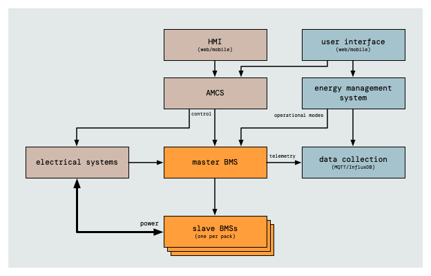
Before we open the hood on the BMS, let's have a look at the surroundings of the BMS. In the text below, we will talk about a so-called "host application". In this section, we'll look at what the host application is and how data flows between the BMS and the systems around it. The systems drawn are typical and the exact components can vary from installation to installation.

In this diagram, we see that the host application consists of the Alarming, Monitoring and Control System (AMCS) that does direct control, and the energy management system that keeps a high level overview of all the systems.
The energy management system knows of the long term plans and prediction about charge availability and energy demand. It communicates those with the BMS in the form of operation modes of the installation. The BMS uses these modes to plan preheat cycles to prepare batteries for high current charging, for example when a sailing trip is announced, or to put components in sleep mode for extended periods of time, to conserve energy while the ship is docked and generally dormant.
The box labelled electrical systems represent the collection of electrical systems that receive power from the battery pack, or send power to it. Electrical systems can communicate with the battery management system to be informed about optimal usage of the battery packs.
Telemetry is collected outside of the BMS, in a time series database that is designed to accept large volumes of telemetry from many systems in the installation. Some BMSs come with built-in data storage and graphing, but in our experience these are never quite as advanced as purpose-built time series database. Built-in telemetry storage makes it difficult to relate events on the BMS to events in the larger installation, hence the need for an external telemetry solution.
The master BMS is responsible for everything that happens in the entire battery subsystem. To be able to do that, external systems never communicate with the slave BMSs directly. All commands and telemetry are sent to the master. The master controls the slave BMSs in turn. The only exception to this is the power draw by the electrical systems. From a data perspective this is also a request, though done electrically and not via a network-based protocol. For this exception, the slave keeps the master informed and accepts control decisions from the master on power draw.
Battery Management System Responsibilities
With the system overview in mind, let's turn towards the functional requirements for the BMS. This section discussed its responsibilities. We would like to have a compact list. Complexity can always be added later. Joking aside: additional requirements seem to be mostly specialisations of one of the items below.
The responsibilities are listed in a priority order. When in doubt, the BMS should prioritise a lower numbered items over higher numbered requirements.
- protect the safety of the operator or the host application The BMS should raise alarms when safety is compromised or projected to become compromised. This also includes maintaining some buffer capacity that can be requested in case of an emergency.
- protect the battery from exceeding its limits In the case of the host application misbehaving, or an internal fault being detected, the BMS should take measures to ensure the situation does not escalate.
- optimise for Remaining Useful Life (RUL) The BMS should balance the load on the cells, both for charging and discharging, to ensure maximum battery life. It should also keep the cells in their optimal temperature range for operation.
- inform the host application how to make best use of the battery The BMS should for example communicate the optimal charge and discharge speeds.
- be energy efficient Zero has the specific requirement for its components to be energy efficient by themselves. The BMS will have to conserve energy by putting components and subsystems into a low power mode. This is true not only for the users of the electrical power, but also to the battery components and the BMS itself.
- publish telemetry The BMS collects telemetry, but is not responsible for storing or displaying any telemetry. Instead, the data is sent to the MQTT bus, integrating into the rest of the data collection. Such telemetry will include, but is not limited to: all measures currents, voltages and temperatures, state of charge (SoC), state of health (SoH), state of temperature (SoT)
The responsibilities listed are based in part on Overview of batteries and battery management for electric vehicles by Wei Liu, Tobias Placke and K.T. Chau, Battery Management System (BMS) design for Lithium-ion Batteries, A Holistic Approach by Tom Hoeger and BMS priorities | 1.3.1- What is Battery management system (BMS) by Physics Insight.
What the BMS can expect from the host application.
In order to function well, the BMS needs certain information from the host application, mainly so that the BMS can plan ahead for high load charge and discharge sessions.
- planned sequence of operational modes over the coming few days The timeline of operation modes gives the battery management system the chance to preheat batteries to better accept charge from sailing trips. The operational modes are also used by the BMS to put (parts of) the battery systems into sleep mode to conserve energy.
- request for emergency power The saved emergency buffer is still available for use by the host application, but must be requested explicitly.
Functional Decomposition Diagram
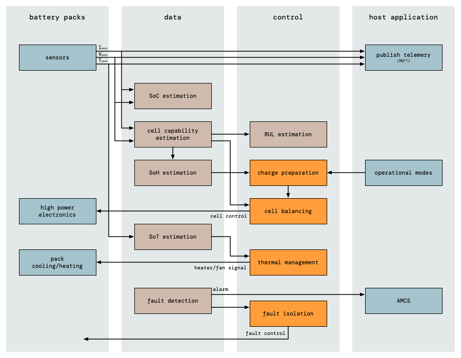
With these responsibilities in mind, let's look at the functional decomposition diagram. This diagram is intended to help structure discussion around BMS design by naming functions and showing how they relate to other functions. The diagram below shows functions as communicating blocks. In your implementation there may be a single component that implements more than one function. It still helps to think of these as separate functions.

To keep the diagram readable, we've left out some of the overarching interactions. For example, each component produces its own stream of telemetry data, all of which goes onto the MQTT bus to the central time series database. The diagram shows only the basic , and handling as an example.
Also, pack control systems are quite specific for the battery pack implementations. This diagram leaves those also to the BMS implementation.
Below, we briefly describe each component's responsibility.
- sensors Each battery pack comes equipped with an array of sensors. Typically, these measure voltage, current and temperature of each cell, but they may also keep track of charge cycle count or other cell- or pack level data.
- high power electronics The high power electronics inside each pack are responsible to switch the cells.
- pack cooling/heating Lithium-ion batteries are quite sensitive to temperature. Each battery pack has a means of cooling and heating the batteries for optimal performance.
- State of Charge (SoC) estimator This component monitors the data coming from the packs and determines the current State of Charge (SoC). This may be a simple calculator, or a more advanced, model based estimator.
- cell capability estimator This estimator is responsible to determine each cell's capabilities over its life. This is necessary for SoH estimation as well as RUL optimisation.
- State of Health (SoH) estimator Predicts the state of health of the battery pack as a whole.
- State of Temperature (SoT) estimator Determines the temperature in each cell and pack. This can be as simple as using the nearest temperature sensor, or as complex as a dynamic thermal model of the system.
- fault detection Detects faults in the battery cells, packs or in the communication in the BMS.
- Remaining Useful Life (RUL) estimation A predictor of the remaining useful life of the battery system as a whole.
- charge preparation Using the cell capabilities and the planned modes of operation, this component determines the actions to be taken to accept the upcoming charge efficiently.
- cell balancing Determines the cell balancing policy in order to optimise RUL as well as operational performance.
- thermal management Monitors the battery pack's thermal state (SoT) and decides what cooling and heating actions to take for optimal performance and RUL.
- fault isolation The BMS has some agency in taking action to avoid faults escalating. The fault isolation determines what actions are needed to protect the user as well as the battery pack from faults.
- publish telemetry This component communicates all telemetry with the host application via MQTT.
- operational modes This component receives the plan with the system as a whole: what operational mode will the system be in and at what timeframe. This information is then used by the BMS to determine high and low load situations and be able to act accordingly.
Closing Words
In this article, we've looked at what a BMS should do and organised its tasks into functional blocks. We organised these into diagrams, showing how they relate and interact.